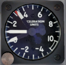
Main Panel Layout
Detailed Description
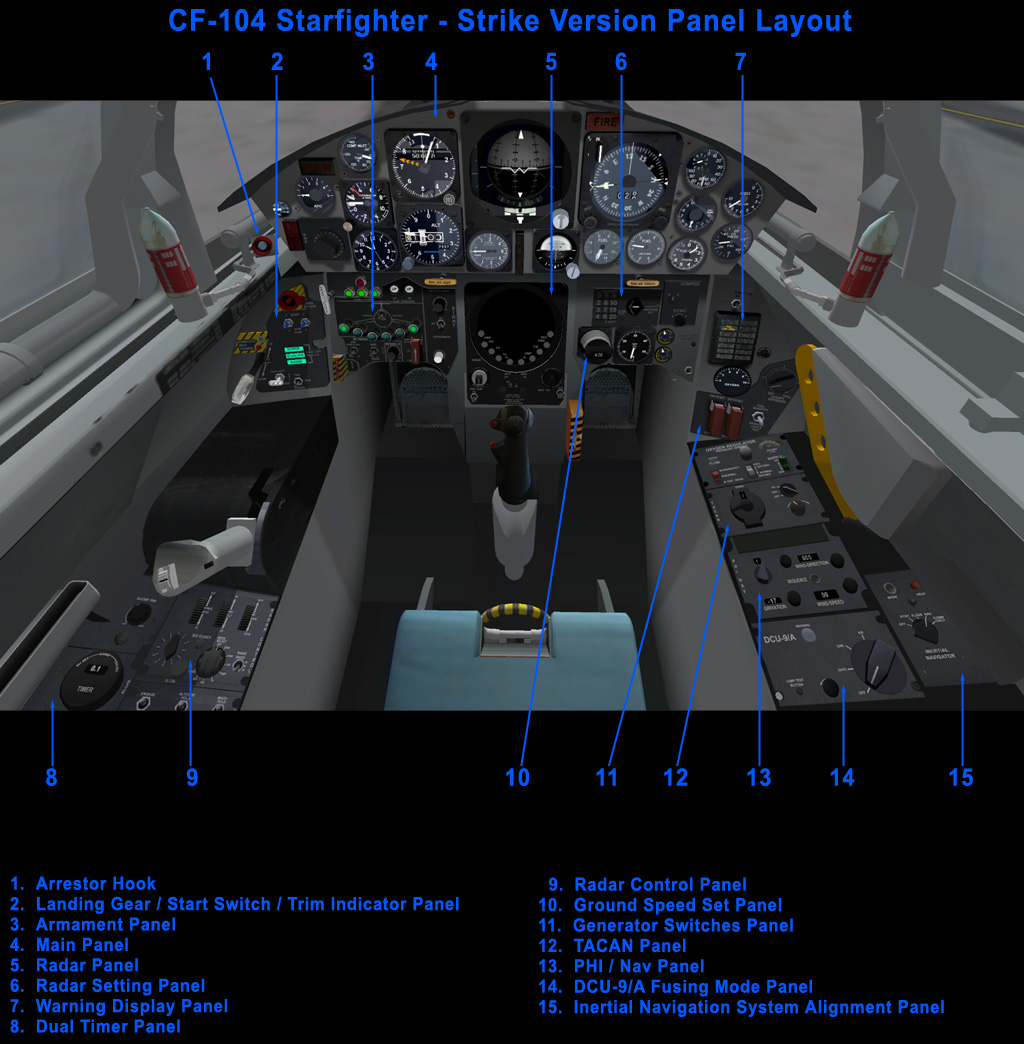
Automatic Pitch Control (APC) Gauge
The
APC gauge reads from 0 to 5 and displays a combination of
Angle-Of-Attack (AOA) and Pitch Rate information to the pilot.
The CF-104 is prone to pitch-up at high AOA and pitch rate so an
automatic pitch control system was developed to provide some warnings
to the pilot when ever the aircraft is approaching dangerous flight
conditions. A stick-shaker will shake the stick to alert the
pilot that he is approaching a high AOA. As the AOA reaches a
dangerous level, a stick-kicker will activate and apply forward
pressure on the stick. The kicker will activate as the APC gauge
displays a reading of 5. If the pilot continues to pull back on
the stick beyond this value, pitch-up is imminent.
The APC reading relates to AOA in this manner. When the APC is
reading a value of zero, the AOA can be between 0 and 3 degrees.
A value of 5 corresponds to approximately 13 degrees AOA.
The pitch-up angle of attack is around 16 degrees. Needless
to say, the APC gauge should be monitored during slow flight and
agressive maneuvering. During landing, it is essential as well to
keep the AOA with safe limits. A value of 3 on the APC during
landing is typical. The stick shaker in the simulator is modeled
as a chattering sound that is played. You will hear this often.
During dogfights, it is common practice to turn hard until the
stick shaker activates.
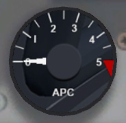
Compressor Inlet Temperature Gauge and Warning Light
The Compressor Inlet Temperature Gauge monitors
engine inlet temperature. Top speeds of the CF-104 are extremely
high and the aircraft will accelerate beyond M 2.3 unless the engine is
throttled back. At high speeds, the inlet temperature can get
very high. Beyond.100 deg C, the warning light marked SLOW will
begin to flash as a warning that the inlet temperature is getting too
hot. Prolonged flight at high inlet temperatures can cause
serious damage to the engine. In flight tests and speed record
attempts, M 2.3 was regularly achieved for short time periods with no
damaging effects on the engine. At higher altitudes and colder
temperatures, the aircraft may be flown at higher Mach numbers and
lower inlet temperatures.
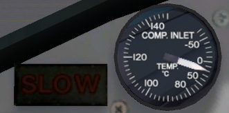
G Meter
The G Meter reads current G load, minimum G load, and maximum G load.
The button on the bottom left of the gauge may be used to reset
the maximum and minimum values back to 1.
UHF Radio Channel Selector
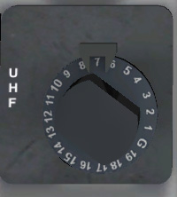
Nineteen preset UHF channels and one Guard channel may be defined for
UHF voice radio. UHF radio is inoperative in this simulation.
Combined Mach / Indicated Airpseed Indicator
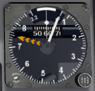
The airspeed indicator combines both Mach number reading and indicated
airspeed reading in knots. Indicated airspeed does not read below
60 knots. There is also a rotating drum in the top part of the
gauge that displays the "tens" value of the airspeed reading to provide
a more precise indication. Along the top of the gauge is a
rotating dial that displays indicated Mach number up to M 2.2.
The push button is inactive in the simulator.
Altimeter
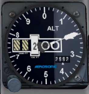
The altimeter has one needle which reads the altitude in hundreds of
feet. The digits in the middle read hundreds, thousands, and
ten-thousands. The knob on the bottom left is used to adjust
barometric pressure.
Attitude Indicator
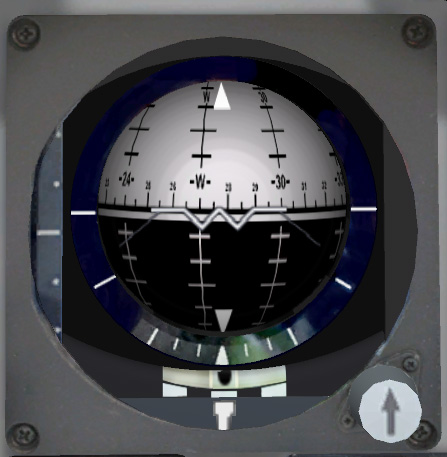
The Attitude Indicator displays several pieces of data. Power to
the attitude indicator is received from the Inertial Navigation System
(INS). The INS is on the right side panel. The INS mode
switch must be turned on in order for the Attitude Indicator to receive
power. The INS detects magnetic heading and sends this data to
the attitude indicator which displays heading along the horizon line of
the ball. See the Aircraft Systems - Navigation System section in the manual for more information on the INS. Besides heading information, the ball also displays pitch angle and roll attitude.
The bottom of the AI incorporates a needle and ball to display yaw information.
On the left side of the gauge is a vertical tape display. The
difference between actual ground speed as determined by the INS and
desired ground speed as entered on the desired ground speed indicator,
to the right of the radar, is displayed on this vertical tape. An
arrow will appear on the tape when the two values are within +/- 9
knots.
The knob on the bottom right of the AI will tilt the ball so can be
adjust as different aircraft attitudes as desired by the pilot to show
level flight.
Position and Homing Indicator (PHI)
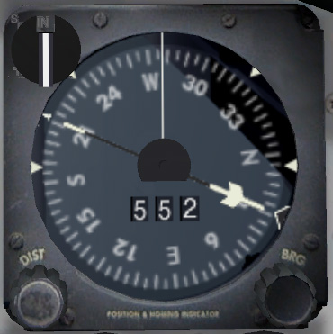
See the Aircraft Systems - Navigation Systems section in the manual for information on this gauge.